
959 Radio
Particle Counter (Scintillator)
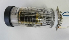
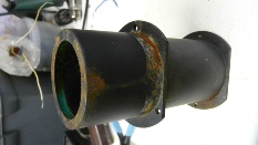
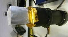
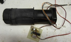
In the cupboard I had a photomultiplier tube which had been scavenged from an old Muirhead fax transmitter. It seemed a shame not to put it to good use. I remembered a long while back a colleague of mine making a particle counter with such a tube. Research on the internet showed that some scintillation material placed in front of the photomultiplier would do the job. A block of scintillation plastic was sourced from Ebay. When a cosmic or nuclear particle hits this material (apart from alpha particles which are stopped by something as thin as a piece of paper) a brief flash of light is produced. This is amplified by the photomultiplier and generates a pulse at its output. Dynode arrays can be disturbed by magnetic fields as low as 0.1 Gauss. Since the earth’s magnetic field averages about 0.5 gauss the PM tube has to be placed in a mu metal enclosure. Luckily the fax machine had one designed for the job. The scintillator material was placed on top of the PM tube and a cardboard tube of a suitable size was made out of A4 sheets and wallpaper paste around a suitable former. This happened to be a CO2 cylinder used to top up my beer barrel padded out with more A4 paper and covered with clingfilm. A black cap from an aerosol can covered the top and a UV LED was inserted to provide test pulses. The whole shebang was painted black to keep out light. It turned out that light still got through as shown by a 50Hz waveform at the anode of the 6J32P. It was painted black again. That cured the problem. Looking at the fax machine handbook the PM tube had a supply that varied under AGC control from 600v to 1200v. I used an HV generator circuit using a 6N6P (Russian near equivalent is probably a 12BY7) to supply 1000v with a feedback system to regulate the supply which the PM tube seemed quite happy with. The pulses were amplified in a 6J32P (Russian EF86) fed to a 6N2P (Russian 12AX7 apart from the heaters) connected as a monostable multivibrator to give the correct pulse width to drive two GS10E dekatron tubes which in turn drove two Russian IN-12 nixie tubes. A further 6N6P was used in the reset circuitry.
The PSU circuit diagram is here.
The signal and HV generator circuit diagram is here.
The dekatron and display circuit diagram is here. Soon
The reset and control circuit diagram is here. Later
There is no explanation for the circuits, they all follow standard tube design.
Russian double triodes are true 6.3v heater types with pin 9 used as an internal shield, so beware if replacing western 12AX7 or similar with Russian 6Nx series.
While this site is under construction, the exact circuit diagrams and component values may change