
959 Radio
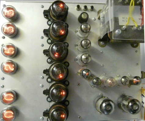
This project was a brilliant excuse to play with some dekatrons and other tubes as well. Some transistors are also put to use also as high voltage drivers for the nixie tubes. Suitable gas filled trigger tubes seem to be unobtainable now. Transistors were also used in the reset circuitry as good use could be made of their PNP characteristics. Valves only come in NPN !!
How a dekatron works
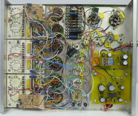
The clock is in five main sections:
1.. Power supply generates +475v for the dektrons, +200v for the interstage coupling tubes, -100v for the reset circuitry and a 100Hz signal (full wave rectified AC) for the second generator. The circuit is here dek_clock_psu.pdf (273 KB).
2..The 1 second generator divides the 100Hz signal down to 1Hz to drive the clock. 1sec_generator.pdf (197 KB).
3..The second counter is a divide by 60 circuit. Reset on the divide by 6 counter is done with transistors, interstage coupling uses 12AT7 tubes. Transistors are used to drive the nixie tubes. sec_counter.pdf (283KB).
4.. The minute counter is a divide by 60 circuit. Reset on the divide by 6 counter is done with transistors, interstage coupling uses 12AT7 tubes. Transistors are used to drive the nixie tubes. min_counter.pdf (283KB).
5. The hour counter has extra circuitry to roll over at 23. Both circuits have provision to set the time. Also included is a test switch. hr_counter.pdf (337KB).